Connections
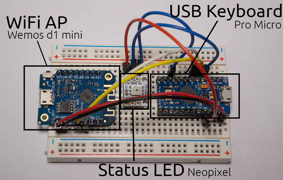
Here’s a map of the pins that need to be connected.
| ESP8266 | Atmega32u4 |
|---|---|
D1 alias GPIO 5 | D3 alias SCL |
D2 alias GPIO 4 | D2 alias SDA |
GND | GND |
Both chips have to be powered in order to work.
To share power between both, you need a voltage regulator that takes 5V and turns it into 3.3V.
It’s because USB runs at 5V but the ESP8266 runs at 3.3V. Luckily most development boards have such a regulator on board.
DO NOT CONNECT ESP8266 VCC to the ATMEGA32u4 VCC, it will kill the ESP826. Instead look for the 5V or VIN pin on your dev board, as those will be connected to the regulator.
| ESP8266 Dev Board | Atmega32u4 |
|---|---|
5V or VIN | RAW, 5V or VIN |
If you like to add a Neopixel (WS2812b) LED:
| Atmega32u4 | Neopixel LED |
|---|---|
7* | DI alias Data, In |
5V alias VCC | 5V alias VCC |
GND | GND |
* The Data pin can be changed later on in the software, pin 7 is just an example.