Display, Buttons & LED
Display
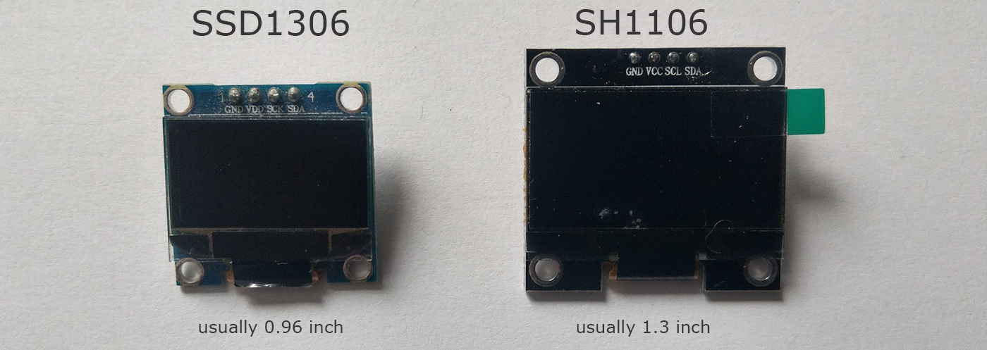
There are 2 types of OLED displays that can be used for this project, the SSD1306 and the SH1106:
And they sometimes come with either I2C or SPI:
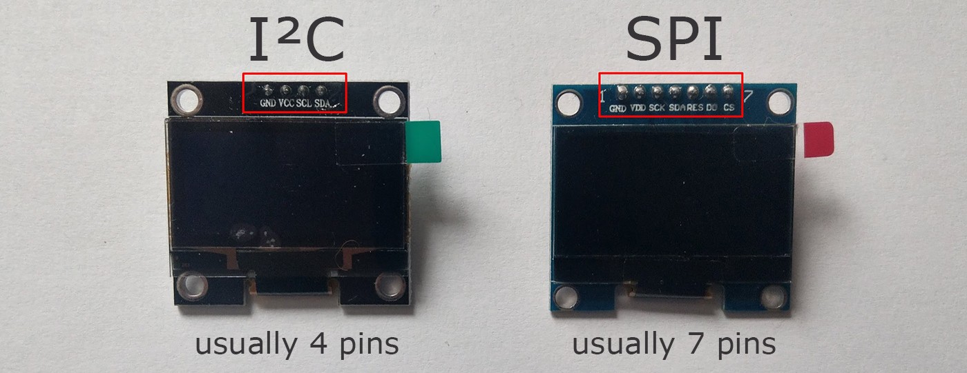
Now for the display it is very important that you know which connection it is using.
I2C can be connected to any GPIO pin (except 16).
The SPI however requires following connections:
| Display | GPIO |
|---|---|
| SCL/CLK/SCK | GPIO 14 (D5) |
| SDA/MOSI | GPIO 13 (D7) |
RST, DC and CS pins can connected to any pin.
Best practice is to make a list of all components and their connections!.
Buttons
The buttons are pretty simple.
You need to connect each of them between a gpio pin and GND.
Like in this Arduino tutorial: https://www.arduino.cc/en/Tutorial/InputPullupSerial
LED
The LED(s) is completley optional. It’s used to give the user a better indication of what the device is currently doing. For example Green = idle, Blue = scanning, RED = deauth attack detected (when scanning).
You can use single digital LEDs, a RGB LED or a neopixel LED (ws2812).
By default the LED on GPIO 16 (NodeMCU on-board LED) and the LED on GPIO 2 (ESP-12 and ESP-07 on-module LED) are used. So be sure to disable them if you want to use those pins for something else.