Wire everything up
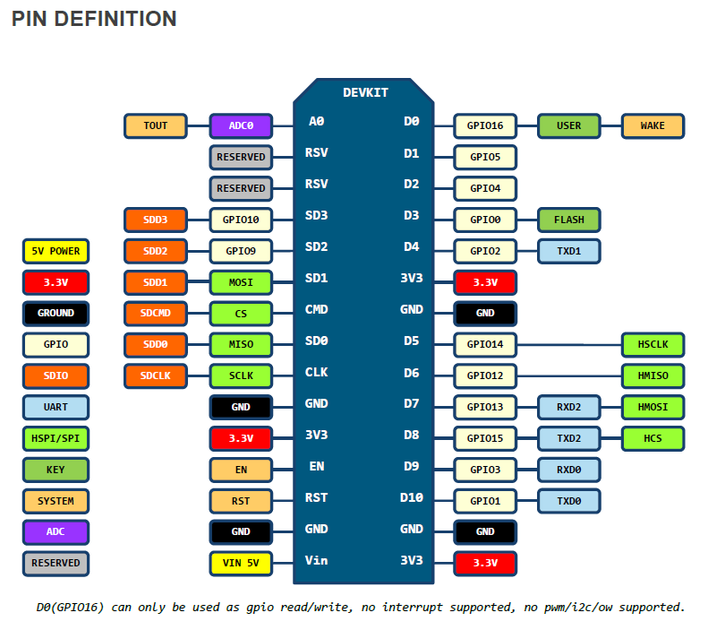
Here is a quick reference of the NodeMCU pinout:
(Click here for a Pinout on the ESP-12, ESP-07 and ESP-01)
Now one important thing is that we have a limited amount of pins and we have to be careful which we use.
Those are the ones we can use for attaching the components:
| NodeMCU Pin | GPIO | Note |
|---|---|---|
| D0 | GPIO 16 | No i2c or pwm, sometimes used for board LED |
| D1 | GPIO 5 | |
| D2 | GPIO 4 | |
| D3 | GPIO 0 | Used for flash button |
| D4 | GPIO 2 | Needs pull-up resistor, used for module LED |
| D5 | GPIO 14 | |
| D6 | GPIO 12 | |
| D7 | GPIO 13 | |
| D8 | GPIO 15 | Needs pull-down resistor |
| D9 | GPIO 3 | RX (Serial) |
| D10 | GPIO 1 | TX (Serial) |
| SD2 | GPIO 9 | Used for Flash |
| SD3 | GPIO 10 | Used for Flash |
A few things are important to note here!
- D0 or GPIO 16 can’t be used for a classical RGB LED (pwm) or for the display (i2c).
- D4 and D8 need resistors? Yes these pins are used for booting the device correctley. That’s where the recommended 2 resistors come in place! Usually the development board already has such in place, but in case you use these pins and run into problems when uploading new code - that might be the reason! So keep in it in mind.
- D9 and D10 are used for serial and are, as such, essential to upload code and debug it. Don’t use these pins unless you know what you’re doing!
- D3 or GPIO 0 is used for the flash button. Usually that’s not a problem, but again… if you run into problems when uploading, keep in mind that the pin is used to get the device into flash mode.
- SD2 and SD3 are used for the on-board SPI flash. You can use them safely as long as you don’t select QIO in the upload/compile settings.
That leaves us with 7 safe to use pins and 4 more which we have to be a bit careful with.
Now you don’t have to be a genius to figure out that if you want to use all 6 buttons (6 pins), a SPI display (4 pins) and a RGB LED (3 pins), 11 pins are not enough.
That’s why it is recommended to use an i2c display (2 pins) or a neopixel/ws2812 (1 pin).
Also don’t forget that you only need 3 buttons, every other button is optional.